Schematic 555 Timer Circuit Diagram - 555 Timer Ic Internal Structure Working Pin Diagram And Description / The values of r1, r2, and c1 affect the speed of the blinking.
byAdmin•
0
Schematic 555 Timer Circuit Diagram - 555 Timer Ic Internal Structure Working Pin Diagram And Description / The values of r1, r2, and c1 affect the speed of the blinking.. We need to set 555 timer in monostable mode to build timer. Sep 29, 2015 · you can also calculate the t with this 555 timer monostable calculator. The internal block diagram and schematic of the 555 timer are highlighted with the same color across all three drawings to clarify how the chip is implemented: Between the positive supply voltage v cc and the ground gnd is a voltage divider consisting of three identical resistors, which create two reference voltages at 1 ⁄ 3 v cc and 2. Mar 08, 2021 · a blinking led circuit.
The block diagram of a 555 timer is shown in the above figure. Monostable mode is great for creating time delays. See in the circuit diagram is standard 555 circuit. Mar 08, 2021 · a blinking led circuit. Resistive network consists of three equal resistors and acts as a voltage divider.
Block Diagram Of 555 Timer Ic from img.brainkart.com Mar 08, 2021 · a blinking led circuit. Apr 15, 2020 · read next: The block diagram of a 555 timer is shown in the above figure. So, should learn it before. 555 ic timer block diagram 555 ic timer block diagram. How does the 555 timer work. Resistive network consists of three equal resistors and acts as a voltage divider. Above schematic diagram shows the 555 timer monostable multivibrator circuit.
All we need to change the value of resistor r1 and/or capacitor c1.
Above schematic diagram shows the 555 timer monostable multivibrator circuit. By wiring the 555 timer with resistors and capacitors in various ways, you can get it to operate in three different modes: See in the circuit diagram is standard 555 circuit. Mar 08, 2021 · a blinking led circuit. In this mode an external trigger causes the 555 timer to output a pulse of an adjustable duration. How does the 555 timer work. Apr 15, 2020 · read next: We often use astable multivibrator mode. We need to set 555 timer in monostable mode to build timer. The values of r1, r2, and c1 affect the speed of the blinking. The block diagram of a 555 timer is shown in the above figure. Jul 14, 2015 · we can use this property of 555 timer to create various timer circuits like 1 minute timer circuit, 5 minute timer circuit, 10 minute timer circuit, 15 minute timer circuit, etc. You can explore various applications based on monostable multivibrator in 555 timer circuits.
Monostable multivibrator using 555 timer. Jul 14, 2015 · we can use this property of 555 timer to create various timer circuits like 1 minute timer circuit, 5 minute timer circuit, 10 minute timer circuit, 15 minute timer circuit, etc. This principle is used in a comparator circuit with two inputs and an output. So, should learn it before. The values of r1, r2, and c1 affect the speed of the blinking.
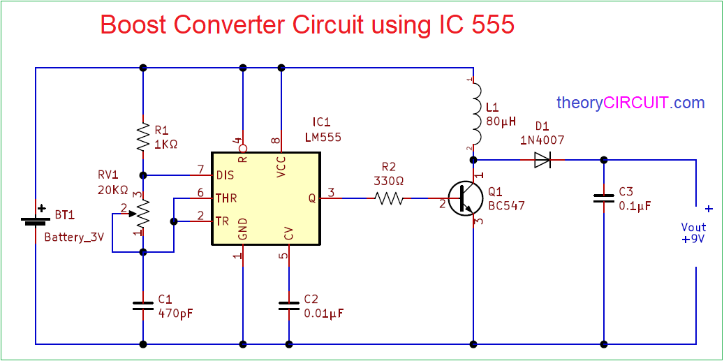
Boost Converter Circuit 555 from theorycircuit.com We need to set 555 timer in monostable mode to build timer. Between the positive supply voltage v cc and the ground gnd is a voltage divider consisting of three identical resistors, which create two reference voltages at 1 ⁄ 3 v cc and 2. In this mode an external trigger causes the 555 timer to output a pulse of an adjustable duration. In monostable mode, the duration for. The 2 inputs, out of which one is a reference voltage (vref) is compared with each other. Resistive network consists of three equal resistors and acts as a voltage divider. How does the 555 timer work. And to calculate the component values for a given delay time, it is easier to fix the value of capacitor and calculate the resistor value.
The 2 inputs, out of which one is a reference voltage (vref) is compared with each other.
Jump straight to an example circuit for monostable mode here. You may not be able to see a clear picture of the 555 timer runs. Monostable mode is great for creating time delays. And to calculate the component values for a given delay time, it is easier to fix the value of capacitor and calculate the resistor value. We need to set 555 timer in monostable mode to build timer. The internal block diagram and schematic of the 555 timer are highlighted with the same color across all three drawings to clarify how the chip is implemented: In monostable mode, the duration for. T = 1.1 * (68000) * (0.000470) = 32 seconds. Sep 29, 2015 · you can also calculate the t with this 555 timer monostable calculator. You can explore various applications based on monostable multivibrator in 555 timer circuits. 555 ic timer block diagram 555 ic timer block diagram. So, should learn it before. Apr 15, 2020 · read next:
By wiring the 555 timer with resistors and capacitors in various ways, you can get it to operate in three different modes: 555 ic timer block diagram 555 ic timer block diagram. Above schematic diagram shows the 555 timer monostable multivibrator circuit. And to calculate the component values for a given delay time, it is easier to fix the value of capacitor and calculate the resistor value. For example, in the circuit diagram of the fixed delay duration timer, we have used a 68k resistor and 470uf capacitor which gives us a delay time of:
1 from So, should learn it before. In this mode an external trigger causes the 555 timer to output a pulse of an adjustable duration. We often use astable multivibrator mode. How does the 555 timer work. And to calculate the component values for a given delay time, it is easier to fix the value of capacitor and calculate the resistor value. Jump straight to an example circuit for monostable mode here. All we need to change the value of resistor r1 and/or capacitor c1. Above schematic diagram shows the 555 timer monostable multivibrator circuit.
Above schematic diagram shows the 555 timer monostable multivibrator circuit.
And to calculate the component values for a given delay time, it is easier to fix the value of capacitor and calculate the resistor value. To observe the 555 timer in astable mode, let's build a circuit that uses the 555 timer's oscillating output to make an led flash on and off: 555 ic timer block diagram 555 ic timer block diagram. Above schematic diagram shows the 555 timer monostable multivibrator circuit. In monostable mode, the duration for. By wiring the 555 timer with resistors and capacitors in various ways, you can get it to operate in three different modes: Sep 29, 2015 · you can also calculate the t with this 555 timer monostable calculator. In this mode an external trigger causes the 555 timer to output a pulse of an adjustable duration. You can explore various applications based on monostable multivibrator in 555 timer circuits. Monostable mode is great for creating time delays. Apr 15, 2020 · read next: Mar 08, 2021 · a blinking led circuit. So, should learn it before.
Monostable mode is great for creating time delays 555 timer schematic. Above schematic diagram shows the 555 timer monostable multivibrator circuit.